Connecting an Amarisoft UE to OCUDU
Overview
The Amarisoft UE simulator (AmariUE) is a commercial software radio solution that supports the simluation of up to 1000s of UE devices. This tutorial outlines how the AmariUE can be used to test and exercise OCUDU. In this example, we will use the open5GS core network to complete the end-to-end 5G network. Usually the gNB and UE connect with each other using physical radios for over-the-air transmissions. However, OCUDU also includes support for virtual radios, which use the ZeroMQ networking library to transfer radio samples between applications. This approach is very useful for development, testing, debugging, CI/CD or for teaching and demonstrating.
This tutorial details two example setups: connecting the OCUDU gNB to AmariUE using virtual radios (ZMQ), and using physical radios (USRP B210).
Hardware and Software Overview
For this tutorial, the following hardware and software are used:
- PC with Ubuntu 22.04 or later
- OCUDU CU/DU
- Amarisoft UE (2021-09-18 or later)
- Two Ettus Research USRP B210s (connected over USB3)
- Open5GS 5G Core
- ZeroMQ
Ideally the USRPs would be connected to a 10 MHz external reference clock or GPSDO, although this is not a strict requirement. We recommend the Leo Bodnar GPSDO.
Amarisoft UE
Amarisoft UE simulator (AmariUE) is a commercial solution that supports functional and performance testing of 5G networks. Acting as a 3GPP compliant LTE, NB-IOT and NR UE, it can simulate hundreds of UEs sharing the same spectrum. For more information visit the Amarisoft website.
Open5GS
For this example we are using Open5GS as the 5G Core.
Open5GS is a C-language Open Source implementation for 5G Core and EPC. The following links will provide you with the information needed to download and setup Open5GS so that it is ready to use with srsRAN 4G:
This tutorial assumes that the 5G Core Network is running on a different machine than the machine running Amarisoft UE.
Installation
ZeroMQ
To install ZMQ, and build OCUDU such that it is recognized, see the installation guide.
Amarisoft UE
Download the appropriate version of Amarisoft UE and install as per steps provided in its install guide.
This tutorial uses version 2023-02-06 of Amarisoft UE, but it can be any version above 2021-09-18.
ZeroMQ driver for Amarisoft UE
These steps should only be completed after compiling OCUDU as mentioned above, as they require the build files of OCUDU and of the Amarisoft UHD RF frontend driver.
Interfacing the Amarisoft UE with OCUDU over ZMQ requires a custom TRX driver implemented by SRS, which can be found in OCUDU source files in ocudu/utils/trx_ocudu, as shwon here.
The Amarisoft UE release folder, amarisoft.2023-02-06.tar.gz, should contain a file called trx_uhd-linux-2023-02-06.tar.gz. The release folder and the sub-file in question should be uncompressed before proceeding.
First, the driver needs to be compiled, do this by running the following commands from ocudu/build :
cmake ../ -DENABLE_EXPORT=TRUE -DENABLE_ZEROMQ=TRUE -DENABLE_TRX_DRIVER=TRUE -DTRX_DRIVER_DIR=<PATH TO trx_uhd-linux-2023-02-06>
make trx_ocudu_test
ctest -R trx_ocudu_test
Make sure CMake finds the file trx_driver.h in the specified folder. CMake should print the following:
-- Found trx_driver.h in TRX_DRIVER_DIR=/home/user/amarisoft/2021-03-15/trx_uhd-linux-2021-03-15/trx_driver.h
A symbolic link must be done for the UE application to load the driver. From the Amarisoft UE build folder run the following command:
ln -s ocudu/build/utils/trx_ocudu/libtrx_ocudu.so trx_ocudu.so
ZeroMQ-based Setup
In this section, we describe the steps required to configure the ZMQ-based RF driver in both gNB and AmariUE. The following diagram presents the setup architecture:

Configuration
The following config files were modified to use ZMQ-based RF driver:
- gNB FDD band 7 config
- gNB TDD band 78 config
- Single UE config FDD band 7
- Single UE config TDD band 78
- Multiple UEs config FDD band 7
- Multiple UEs config TDD band 78
Details of the modifications made are outlined in following sections.
OCUDU
Modify the amf within the cu_cp section with the IP of AMF and IP to which gNB needs to bind in order to connect to AMF. You will also need to define the TA list for the CU-cp:
cu_cp:
  amf:
    addr: 172.22.0.10                 # The address or hostname of the AMF.
    bind_addr: 172.22.0.1             # A local IP that the gNB binds to for traffic from the AMF.
    supported_tracking_areas:         # Configure the TA associated with the CU-CP
      - tac: 7
        plmn_list:
          - plmn: "00101"
            tai_slice_support_list:
              - sst: 1
Modify the ru_sdr section with IPs from which gNB sends and receives radio samples via ZMQ driver:
ru_sdr:
  device_driver: zmq
  device_args:   tx_port=tcp://10.53.1.1:5000,rx_port=tcp://10.53.1.2:6000
Amarisoft UE
Modify the rf_driver section of Amarisoft UE configuration with IPs from which UE sends and receives radio samples via ZMQ driver:
rf_driver: {
  name:      "ocudu",
  args:      "",
  tx_port0:  "tcp://10.53.1.2:6000",
  rx_port0:  "tcp://10.53.1.1:5000",
  log_level: "info"
},
Then, set the gain parameters as follows:
tx_gain: 0,
rx_gain: 0,
Make sure the CELL_BANDWIDTH matches that on gNB configuration file:
#define CELL_BANDWIDTH 10
Add sample_rate: 61.44, in the cell entry under cells section:
sample_rate: 61.44,
Then, set N_ANTENNA_DL to 1:
#define N_ANTENNA_DL 1
Note that the following (default) SIM Credentials and APN are used:
sim_algo: "milenage",
imsi: "001019123456799",
K: "00112233445566778899aabbccddeeff",
opc: "63bfa50ee6523365ff14c1f45f88737d",
apn: "internet",
Open5GS 5G Core
As highlighted above, the Open5GS Quickstart Guide provides a comprehensive overview of how to configure Open5GS to run as a 5G Core.
The main modifications needed are:
- Change the TAC in the AMF config to 7
- Check that the NGAP, and GTPU addresses are all correct. This is done in the AMF and UPF config files.
- It is also a good idea to make sure the PLMN values are consistent across all of the above files and the UE config file.
The final step is to register the UE to the list of subscribers through the Open5GS WebUI. The values for each field should match what is in the Amarisoft UE config file, under the ue_list section.
Make sure to correctly configure the APN, if this is not done correctly the UE will not connect to the internet.
It is important to run Amarisoft UE and 5G Core in different machine or at least in different network namespaces. This is because both the 5GC and UE will be sharing the same network configuration, i.e. routing tables etc. Because the UE receives an IP address from the 5GC’s subnet, the Linux kernel would bypass the TUN interfaces when routing traffic between both ends.
Running the 5G Network
The following order should be used when running the network:
- 5GC
- gNB
- UE
Open5gs 5G Core
Once the steps from the Open5GS Quickstart Guide are followed you do not need to do any more to bring the core online. It will run in the background. Make sure to restart the relevant daemons after making any changes to the config files.
OCUDU
Run the gNB from its build directory, using the configuration file provided:
sudo ./apps/gnb/gnb -c gnb_rf_zmq_fdd_n7_10mhz.yml
The console output should be similar to the following:
Available radio types: uhd and zmq.

--== OCUDU gNB (commit 2c67c80) ==--

Connecting to AMF on 172.22.0.10:38412
Cell pci=1, bw=10 MHz, dl_arfcn=536020 (n7), dl_freq=2680.1 MHz, dl_ssb_arfcn=535930, ul_freq=2560.1 MHz

==== gNodeB started ===
Type <t> to view trace
The Connecting to AMF on 172.22.0.10:38412 message indicates that gNB initiated a connection to the core.
If the connection attempt is successful, the following (or similar) will be displayed on the Open5GS console:
amf      | 04/23 14:38:26.459: [amf] INFO: gNB-N2 accepted[172.22.0.1]:49428 in ng-path module (../src/amf/ngap-sctp.c:113)
amf      | 04/23 14:38:26.459: [amf] INFO: gNB-N2 accepted[172.22.0.1] in master_sm module (../src/amf/amf-sm.c:741)
amf      | 04/23 14:38:26.459: [amf] INFO: [Added] Number of gNBs is now 1 (../src/amf/context.c:1178)
amf      | 04/23 14:38:26.459: [amf] INFO: gNB-N2[172.22.0.1] max_num_of_ostreams : 30 (../src/amf/amf-sm.c:780)
Amarisoft UE
Lastly we can launch the UE, with root permissions to create the TUN device.
/root/ue/lteue /root/ue/config/ue-nr-sa-fdd-n7-zmq-single-ue.cfg
The above command should start the UE and attach it to the core network.
If UE connects successfully to the network, the following (or similar) should be displayed on the console:
amariue  | RF0: sample_rate=61.440 MHz dl_freq=2680.100 MHz ul_freq=2560.100 MHz (band n7) dl_ant=1 ul_ant=1
amariue  | (ue) Cell 0: SIB found
amariue  | UE PDN TUN iface requested: ue_id: ue1, pdn_id: 0, ifname: ue1-pdn0, ipv4_addr: 192.168.100.2, ipv4_dns: 8.8.4.4, ipv6_local_addr: , ipv6_dns:
amariue  | Created iface ue1-pdn0 with 192.168.100.2
It is clear that the connection has been made successfully once the UE has been assigned an IP, this is seen in PDU Session Establishment successful. IP: 192.168.100.2.
The NR connection is then confirmed with the RRC NR reconfiguration successful. message.
Testing the Network
Here, we demonstrate how to use ping and iPerf3 tools to test the connectivity and throughput in the network.
Ping
To exchange traffic in the downlink direction, i.e. from the the 5GC (UPF), just run ping as usual on the command line, e.g.:
ping 192.168.100.2
In order to generate traffic in the uplink direction it is important to run the ping command
using the TUN interface of UE (e.g. tun0 created once Amarisoft UE attaches to 5G network).
ip netns exec ue0 ping 192.168.100.1 -I tun0
iPerf
Downlink
For generating downlink traffic, we run iPerf client on the 5GC (UPF) and server on the UE as follows:
In the UE,
ip netns exec ue0 iperf -u -s -i 1
In the UPF,
iperf -u -c 192.168.100.2 -b 5M -i 1 -t 30
Uplink
And, for uplink traffic, we run iPerf server on the 5GC (UPF) and client on the UE as follows.
In the UPF,
iperf -u -s -i 1
In the UE,
ip netns exec ue0 iperf -u -c 192.168.100.1 -b 5M -i 1 -t 30
iPerf Output
Example server iPerf3 output:
------------------------------------------------------------
Server listening on UDP port 5001
Receiving 1470 byte datagrams
UDP buffer size:  208 KByte (default)
------------------------------------------------------------
[  3] local 192.168.100.1 port 5001 connected with 192.168.100.3 port 36039
[ ID] Interval       Transfer     Bandwidth        Jitter   Lost/Total Datagrams
[  3]  0.0- 1.0 sec   629 KBytes  5.15 Mbits/sec   6.188 ms    0/  438 (0%)
[  3]  1.0- 2.0 sec   431 KBytes  3.53 Mbits/sec   2.656 ms    0/  300 (0%)
[  3]  2.0- 3.0 sec   866 KBytes  7.09 Mbits/sec   2.690 ms    0/  603 (0%)
[  3]  3.0- 4.0 sec   589 KBytes  4.82 Mbits/sec   8.544 ms    0/  410 (0%)
[  3]  4.0- 5.0 sec   693 KBytes  5.68 Mbits/sec   2.879 ms    0/  483 (0%)
[  3]  5.0- 6.0 sec   637 KBytes  5.22 Mbits/sec   2.583 ms    0/  444 (0%)
[  3]  6.0- 7.0 sec   500 KBytes  4.09 Mbits/sec  15.044 ms    0/  348 (0%)
[  3]  7.0- 8.0 sec   784 KBytes  6.42 Mbits/sec   2.792 ms    0/  546 (0%)
[  3]  8.0- 9.0 sec   637 KBytes  5.22 Mbits/sec   9.773 ms    0/  444 (0%)
[  3]  9.0-10.0 sec   600 KBytes  4.92 Mbits/sec  10.407 ms    0/  418 (0%)
[  3] 10.0-11.0 sec   683 KBytes  5.60 Mbits/sec   2.029 ms    0/  476 (0%)
[  3] 11.0-12.0 sec   637 KBytes  5.22 Mbits/sec  11.048 ms    0/  444 (0%)
[  3] 12.0-13.0 sec   643 KBytes  5.27 Mbits/sec   2.563 ms    0/  448 (0%)
[  3] 13.0-14.0 sec   626 KBytes  5.13 Mbits/sec   3.593 ms    0/  436 (0%)
[  3] 14.0-15.0 sec   593 KBytes  4.86 Mbits/sec   8.771 ms    0/  413 (0%)
[  3] 15.0-16.0 sec   669 KBytes  5.48 Mbits/sec   1.940 ms    0/  466 (0%)
[  3] 16.0-17.0 sec   501 KBytes  4.10 Mbits/sec   9.604 ms    0/  349 (0%)
[  3] 17.0-18.0 sec   813 KBytes  6.66 Mbits/sec   2.372 ms    0/  566 (0%)
[  3] 18.0-19.0 sec   637 KBytes  5.22 Mbits/sec   2.671 ms    0/  444 (0%)
[  3] 19.0-20.0 sec   632 KBytes  5.17 Mbits/sec   3.903 ms    0/  440 (0%)
[  3] 20.0-21.0 sec   606 KBytes  4.96 Mbits/sec   2.835 ms    0/  422 (0%)
[  3] 21.0-22.0 sec   678 KBytes  5.55 Mbits/sec   2.643 ms    0/  472 (0%)
[  3] 22.0-23.0 sec   649 KBytes  5.32 Mbits/sec   2.577 ms    0/  452 (0%)
[  3]  0.0-23.6 sec  14.7 MBytes  5.25 Mbits/sec   2.420 ms    0/10510 (0%)
Example client iPerf3 output:
------------------------------------------------------------
Client connecting to 192.168.100.1, UDP port 5001
Sending 1470 byte datagrams, IPG target: 2243.04 us (kalman adjust)
UDP buffer size:  208 KByte (default)
------------------------------------------------------------
[  3] local 192.168.100.3 port 36039 connected with 192.168.100.1 port 5001
[ ID] Interval       Transfer     Bandwidth
[  3]  0.0- 1.0 sec   642 KBytes  5.26 Mbits/sec
[  3]  1.0- 2.0 sec   640 KBytes  5.24 Mbits/sec
[  3]  2.0- 3.0 sec   640 KBytes  5.24 Mbits/sec
[  3]  3.0- 4.0 sec   640 KBytes  5.24 Mbits/sec
[  3]  4.0- 5.0 sec   640 KBytes  5.24 Mbits/sec
[  3]  5.0- 6.0 sec   639 KBytes  5.23 Mbits/sec
[  3]  6.0- 7.0 sec   640 KBytes  5.24 Mbits/sec
[  3]  7.0- 8.0 sec   640 KBytes  5.24 Mbits/sec
[  3]  8.0- 9.0 sec   640 KBytes  5.24 Mbits/sec
[  3]  9.0-10.0 sec   640 KBytes  5.24 Mbits/sec
[  3] 10.0-11.0 sec   640 KBytes  5.24 Mbits/sec
[  3] 11.0-12.0 sec   639 KBytes  5.23 Mbits/sec
[  3] 12.0-13.0 sec   640 KBytes  5.24 Mbits/sec
[  3] 13.0-14.0 sec   640 KBytes  5.24 Mbits/sec
[  3] 14.0-15.0 sec   640 KBytes  5.24 Mbits/sec
[  3] 15.0-16.0 sec   640 KBytes  5.24 Mbits/sec
[  3] 16.0-17.0 sec   639 KBytes  5.23 Mbits/sec
[  3] 17.0-18.0 sec   640 KBytes  5.24 Mbits/sec
[  3] 18.0-19.0 sec   640 KBytes  5.24 Mbits/sec
[  3] 19.0-20.0 sec   640 KBytes  5.24 Mbits/sec
[  3] 20.0-21.0 sec   640 KBytes  5.24 Mbits/sec
gNB Console Output
Following console output was taken while performing UL iperf test:
-----------------------DL----------------|------------------UL--------------------
pci rnti  cqi  mcs  brate   ok  nok  (%) | pusch  mcs  brate   ok  nok  (%)    bsr
  1 4601   15   27   5.8k   10    0   0% |  65.5   28    11M  396    0   0%  5.45k
  1 4601   15   27   5.8k    9    0   0% |  65.5   28   5.7M  253    0   0%  10.6k
  1 4601   15   27   5.2k   10    0   0% |  65.5   28   5.8M  247    0   0%  1.04k
  1 4601   15   27   5.8k   10    0   0% |  65.5   28   8.2M  351    0   0%    0.0
  1 4601   15   27   5.8k   10    0   0% |  65.5   28   6.4M  265    0   0%  5.45k
  1 4601   15   27   5.8k   10    0   0% |  65.5   28   5.8M  255    0   0%  5.45k
  1 4601   15   27   5.8k   10    0   0% |  65.5   28   5.0M  246    0   0%   108k
  1 4601   15   27   5.8k   10    0   0% |  65.5   28    11M  412    0   0%    0.0
  1 4601   15   27   5.8k   10    0   0% |  65.5   28   4.9M  234    0   0%  7.59k
  1 4601   15   27   5.8k   10    0   0% |  65.5   28   9.3M  347    0   0%  10.6k
  1 4601   15   27   5.8k   10    0   0% |  65.5   28   6.7M  278    0   0%  5.45k
Packet Capture
Configuring Amarisoft for multiple UEs
The following config files were modified for simulating multiple UEs:
The main modifications needed are:
- Set
multi_ueto true. - Add multiple entries with UE details (IMSI, K, OPc etc.) under
ue_list. - Add
global_timing_advance: 0in the cell entry undercellssection. - Add the following configuration under each entry in
ue_listand increase the value ofstart_timefor each UE to have a staggered UE bring up.
sim_events: [
  {
    event: "power_on",
    start_time: 0,
  },
]
When multi_ue to false, make sure to have only one entry in ue_list.
Make sure to configure all the subscribers through the Open5GS WebUI, before attempting to attach UEs.
Over-the-air Setup
In this section, we describe the steps required to configure the SDR RF driver in both gNB and Amarisoft UE. The following diagram presents the setup architecture:

Configuration
You can find a configuration file for this example in the configs folder of the OCUDU source files. You can also find it here.
You can download the AmariUE configs here:
Details of the modifications made compared to ZMQ setup are outlined in following sections.
OCUDU
Modify the ru_sdr section to send and receive radio samples via UHD driver:
ru_sdr:
  device_driver: uhd
  device_args: type=b200,num_recv_frames=64,num_send_frames=64
  srate: 11.52
  otw_format: sc12
  tx_gain: 80
  rx_gain: 40
Amarisoft UE
Modify the rf_driver section of Amarisoft UE configuration to send and receive radio samples via UHD driver:
rf_driver: {
    name: "uhd",
    sync: "none",
#if CELL_BANDWIDTH < 5
    args: "send_frame_size=512,recv_frame_size=512",
#elif CELL_BANDWIDTH == 5
    args: "send_frame_size=1024,recv_frame_size=1024",
#elif CELL_BANDWIDTH == 10
    args: "",
#elif CELL_BANDWIDTH > 10
    args: "num_recv_frames=64,num_send_frames=64",
    dl_sample_bits: 12,
    ul_sample_bits: 12,
#endif
    rx_antenna: "rx",
},
Then, set the gain parameters as follows:
tx_gain: 75.0, /* TX gain (in dB) B2x0: 0 to 89.8 dB */
rx_gain: 40.0, /* RX gain (in dB) B2x0: 0 to 73 dB */
And the tx timing offset:
{
 ...
cell_groups: [{
  tx_time_offset: -150,
  ...
}],
...
}
Make sure the CELL_BANDWIDTH matches that on gNB configuration file:
#define CELL_BANDWIDTH 10
Then, set N_ANTENNA_DL to 1:
#define N_ANTENNA_DL 1
Running the 5G Network
The following order should be used when running the network:
- 5GC
- gNB
- UE
Open5gs 5G Core
Running the 5GC is same as in the ZMQ based setup.
OCUDU
Let’s now launch the gNB from its build directory.
sudo ./apps/gnb/gnb -c gnb_rf_b210_tdd_n78_20mhz.yml
The console output should be similar as follows:
Available radio types: uhd and zmq.

--== OCUDU gNB (commit 87c3fe355) ==--

Connecting to AMF on 172.22.0.10:38412
[INFO] [UHD] linux; GNU C++ version 11.3.0; Boost_107400; UHD_4.4.0.0-0ubuntu1~jammy1
[INFO] [LOGGING] Fastpath logging disabled at runtime.
Making USRP object with args 'type=b200'
[INFO] [B200] Detected Device: B210
[INFO] [B200] Operating over USB 3.
[INFO] [B200] Initialize CODEC control...
[INFO] [B200] Initialize Radio control...
[INFO] [B200] Performing register loopback test...
[INFO] [B200] Register loopback test passed
[INFO] [B200] Performing register loopback test...
[INFO] [B200] Register loopback test passed
[INFO] [B200] Setting master clock rate selection to 'automatic'.
[INFO] [B200] Asking for clock rate 16.000000 MHz...
[INFO] [B200] Actually got clock rate 16.000000 MHz.
[INFO] [MULTI_USRP] Setting master clock rate selection to 'manual'.
[INFO] [B200] Asking for clock rate 11.520000 MHz...
[INFO] [B200] Actually got clock rate 11.520000 MHz.
Cell pci=1, bw=10 MHz, dl_arfcn=632628 (n78), dl_freq=3489.42 MHz, dl_ssb_arfcn=632640, ul_freq=3489.42 MHz

==== gNodeB started ===
Type <t> to view trace
Amarisoft UE
Lastly we can launch the UE, with root permissions to create the TUN device.
/root/ue/lteue /root/ue/config/ue-nr-sa-tdd-n78-b210-single-ue.cfg
The above command should start the UE and attach it to the core network. If UE connects successfully to the network, the following (or similar) should be displayed on the console:
[INFO] [UHD] linux; GNU C++ version 9.2.1 20200304; Boost_107100; UHD_3.15.0.0-2build5
[INFO] [MPMD FIND] Found MPM devices, but none are reachable for a UHD session. Specify find_all to find all devices.
[INFO] [B200] Detected Device: B210
[INFO] [B200] Operating over USB 3.
[INFO] [B200] Initialize CODEC control...
[INFO] [B200] Initialize Radio control...
[INFO] [B200] Performing register loopback test...
[INFO] [B200] Register loopback test passed
[INFO] [B200] Performing register loopback test...
[INFO] [B200] Register loopback test passed
[INFO] [B200] Setting master clock rate selection to 'automatic'.
[INFO] [B200] Asking for clock rate 16.000000 MHz...
[INFO] [B200] Actually got clock rate 16.000000 MHz.
[INFO] [MULTI_USRP] Setting master clock rate selection to 'manual'.
[INFO] [B200] Asking for clock rate 11.520000 MHz...
[INFO] [B200] Actually got clock rate 11.520000 MHz.
RF0: sample_rate=11.520 MHz dl_freq=3489.420 MHz ul_freq=3489.420 MHz (band n78) dl_ant=1 ul_ant=1
(ue) Warning: config/ru_sdr/config_tdd.cfg:25: unused property 'tx_time_offset'
[INFO] [MULTI_USRP]     1) catch time transition at pps edge
[INFO] [MULTI_USRP]     2) set times next pps (synchronously)
Chan Gain(dB)   Freq(MHz)
 TX1     70.0 3489.420000
 RX1     40.0 3489.420000
Cell 0: SIB found
And, once connected you can use the Amarisoft UE command line tool to verify whether its attached to cell as follows:
(ue) cells
Cell #0 / NR:
  PCI:    1
  TDD:    config=0, ssf=0
  EARFCN: DL=632628 UL=632628
  RB:     DL=24 UL=24
Testing the Network
Here, we demonstrate how to use ping and iPerf3 tools to test the connectivity and throughput in the network.
Ping
To exchange traffic in the downlink direction, i.e. from the the 5GC (UPF), just run ping as usual on the command line, e.g.:
ping 192.168.100.2
In order to generate traffic in the uplink direction it is important to run the ping command
using the TUN interface of UE (e.g. tun0 created once Amarisoft UE attaches to 5G network).
ip netns exec ue0 ping 192.168.100.1 -I tun0
iPerf
For generating downlink traffic, we run iperf client on the 5GC (UPF) and server on the UE as follows:
In the UE,
ip netns exec ue0 iperf -u -s -i 1
In the UPF,
iperf -u -c 192.168.100.2 -b 10M -i 1 -t 60
And, for uplink traffic, we run iperf server on the 5GC (UPF) and client on the UE as follows.
In the UPF,
iperf -u -s -i 1
In the UE,
ip netns exec ue0 iperf -u -c 192.168.100.1 -b 3M -i 1 -t 60
iPerf Output
Example server iPerf3 output:
------------------------------------------------------------
Server listening on UDP port 5001
Receiving 1470 byte datagrams
UDP buffer size: 32.0 MByte (default)
------------------------------------------------------------
[  3] local 10.45.0.52 port 5001 connected with 10.45.0.1 port 33894
[ ID] Interval       Transfer     Bandwidth        Jitter   Lost/Total Datagrams
[  3]  0.0- 1.0 sec  1.25 MBytes  10.5 Mbits/sec   0.838 ms    0/  893 (0%)
[  3]  1.0- 2.0 sec  1.25 MBytes  10.5 Mbits/sec   0.909 ms    0/  892 (0%)
[  3]  2.0- 3.0 sec  1.25 MBytes  10.5 Mbits/sec   0.839 ms    0/  891 (0%)
[  3]  3.0- 4.0 sec  1.25 MBytes  10.5 Mbits/sec   0.905 ms    0/  892 (0%)
[  3]  4.0- 5.0 sec  1.25 MBytes  10.5 Mbits/sec   0.871 ms    3/  892 (0.34%)
[  3]  5.0- 6.0 sec  1.25 MBytes  10.5 Mbits/sec   0.878 ms    0/  891 (0%)
[  3]  6.0- 7.0 sec  1.25 MBytes  10.5 Mbits/sec   0.922 ms    0/  892 (0%)
[  3]  7.0- 8.0 sec  1.25 MBytes  10.5 Mbits/sec   0.921 ms    0/  892 (0%)
[  3]  8.0- 9.0 sec  1.25 MBytes  10.5 Mbits/sec   0.842 ms    0/  891 (0%)
[  3]  0.0-10.0 sec  12.5 MBytes  10.5 Mbits/sec   0.932 ms    3/ 8917 (0.034%)
Example client iPerf3 output:
------------------------------------------------------------
Client connecting to 10.45.0.52, UDP port 5001
Sending 1470 byte datagrams, IPG target: 1121.52 us (kalman adjust)
UDP buffer size: 32.0 MByte (default)
------------------------------------------------------------
[  3] local 10.45.0.1 port 33894 connected with 10.45.0.52 port 5001
[ ID] Interval       Transfer     Bandwidth
[  3]  0.0- 1.0 sec  1.25 MBytes  10.5 Mbits/sec
[  3]  1.0- 2.0 sec  1.25 MBytes  10.5 Mbits/sec
[  3]  2.0- 3.0 sec  1.25 MBytes  10.5 Mbits/sec
[  3]  3.0- 4.0 sec  1.25 MBytes  10.5 Mbits/sec
[  3]  4.0- 5.0 sec  1.25 MBytes  10.5 Mbits/sec
[  3]  5.0- 6.0 sec  1.25 MBytes  10.5 Mbits/sec
[  3]  6.0- 7.0 sec  1.25 MBytes  10.5 Mbits/sec
[  3]  7.0- 8.0 sec  1.25 MBytes  10.5 Mbits/sec
[  3]  8.0- 9.0 sec  1.25 MBytes  10.5 Mbits/sec
[  3]  0.0-10.0 sec  12.5 MBytes  10.5 Mbits/sec
[  3] Sent 8917 datagrams
[  3] Server Report:
[  3]  0.0-10.0 sec  12.5 MBytes  10.5 Mbits/sec   0.931 ms    3/ 8917 (0.034%)
gNB Console Output
Following console output was taken while performing DL iperf test:
-----------------------DL----------------|------------------UL--------------------
pci rnti  cqi  mcs  brate   ok  nok  (%) | pusch  mcs  brate   ok  nok  (%)    bsr
  1 4601    4    0      0    0    0   0% | -21.3    0   3.0k    0    5   0%    0.0
  1 4602   15   28    11M  973    0   0% |   n/a    0      0    0    0   0%    0.0
  1 4601    4    0      0    0    0   0% |   n/a    0      0    0    0   0%    0.0
  1 4602   15   28    11M  976    0   0% |   n/a    0      0    0    0   0%    0.0
  1 4601    4    0      0    0    0   0% |   n/a    0      0    0    0   0%    0.0
  1 4602   15   28    11M  976    0   0% |   n/a    0      0    0    0   0%    0.0
  1 4601    4    0      0    0    0   0% |   n/a    0      0    0    0   0%    0.0
  1 4602   15   28    11M  973    9   0% |  27.4   28   4.4k    1    0   0%    0.0
  1 4601    4    0      0    0    0   0% |   n/a    0      0    0    0   0%    0.0
  1 4602   15   28    11M  973    1   0% |  28.5   28   4.4k    1    0   0%    0.0
  1 4601    4    0      0    0    0   0% | -21.0    0   3.0k    0    5   0%    0.0
  1 4602   15   28    11M  980    0   0% |  30.3   28   4.4k    1    0   0%    0.0
  1 4601    4    0      0    0    0   0% |   n/a    0      0    0    0   0%    0.0
  1 4602   15   28    11M  972    0   0% |   n/a    0      0    0    0   0%    0.0
  1 4601    4    0      0    0    0   0% |   n/a    0      0    0    0   0%    0.0
  1 4602   15   28    11M  976    0   0% |   n/a    0      0    0    0   0%    0.0
  1 4601    4    0      0    0    0   0% |   n/a    0      0    0    0   0%    0.0
  1 4602   15   28   8.1M  732    0   0% |  25.9   28   414k   43    4   8%    0.0
Packet Capture
The RRC Inactive Functionality
OCUDU supports suspending an NR SA UE into RRC Inactive and resuming the UE starting with release v26.04.
This section uses the Amarisoft NR Core because the AMF must provide Core Network Assistance Information For Inactive to the gNB for this procedure. Open5GS currently does not support the RRC Inactive procedure. See the issue tracker for more information.
Configure the Amarisoft core by following the Amarisoft NR core integration guide.
Enable Core Network Assistance Information
Set cn_assistance_info_support in the Amarisoft NR core configuration file:
cn_assistance_info_support: true,
This setting forces the AMF to provide Core Network Assistance Information during the NGAP initial context setup procedure.
Enable RRC Inactive support in AmariUE
Add the following parameter to the NR UE entry in the ue_list block:
rrc_inactive_support: true,
This parameter configures AmariUE to advertise support for RRC Inactive.
Enable RRC Inactive in OCUDU
Configure the OCUDU CU-CP as shown below:
cu_cp:
  inactivity_timer: 10
  enable_rrc_inactive: true
  ran_paging_cycle: 32
  t380: 5
The inactivity_timer parameter triggers the transition from RRC_CONNECTED to RRC_INACTIVE.
Test RRC Inactive
Start the components in the following order:
Amarisoft NR Core
Run this command directly from the ltemme release folder:
./ltemme config/mme.ocudu.rrcinactive.cfg
OCUDU
Run this command from the build folder:
sudo ./apps/gnb/gnb -c gnb_rf_x310_tdd_n78_40mhz_rrcinactive.yml
Amarisoft UE
Run this command from the lteue release folder:
/root/lteue-linux-2025-09-19/lteue /root/lteue-linux-2025-09-19/config/ue-nr-sa-tdd-n78-x310-single-ue-rrcinactive.cfg
After starting the UE and attaching to the core network, the UE RRC_STATE shows running (Connected state):
(ue) ue 1
        # UE_ID CL RNTI    RRC_STATE               EMM_STATE #ERAB IP_ADDR
  NR          1  0 4601      running              registered     1 192.168.4.2 CID 0
After the inactivity timer expires, the UE state changes to inactive. In the terminal, this is shown as below:
(ue) ue 1
        # UE_ID CL RNTI    RRC_STATE               EMM_STATE #ERAB IP_ADDR
  NR          1  0 4601     inactive              registered     1 192.168.4.2 CID 0
Wait one RNA update period (5 minutes). Execute the ping command using the pdn0 TUN interface of the UE to generate uplink traffic:
ip netns exec ue1 ping 192.168.4.1 -I pdn0
PING 192.168.4.1 (192.168.4.1) from 192.168.4.2 pdn0: 56(84) bytes of data.
64 bytes from 192.168.4.1: icmp_seq=1 ttl=64 time=76.4 ms
64 bytes from 192.168.4.1: icmp_seq=2 ttl=64 time=34.1 ms
64 bytes from 192.168.4.1: icmp_seq=3 ttl=64 time=33.0 ms
64 bytes from 192.168.4.1: icmp_seq=4 ttl=64 time=32.0 ms
The UE resumes the RRC connection, and the UE switches back from RRC_INACTIVE to RRC_CONNECTED state.
Verify Core Network Assistance Information
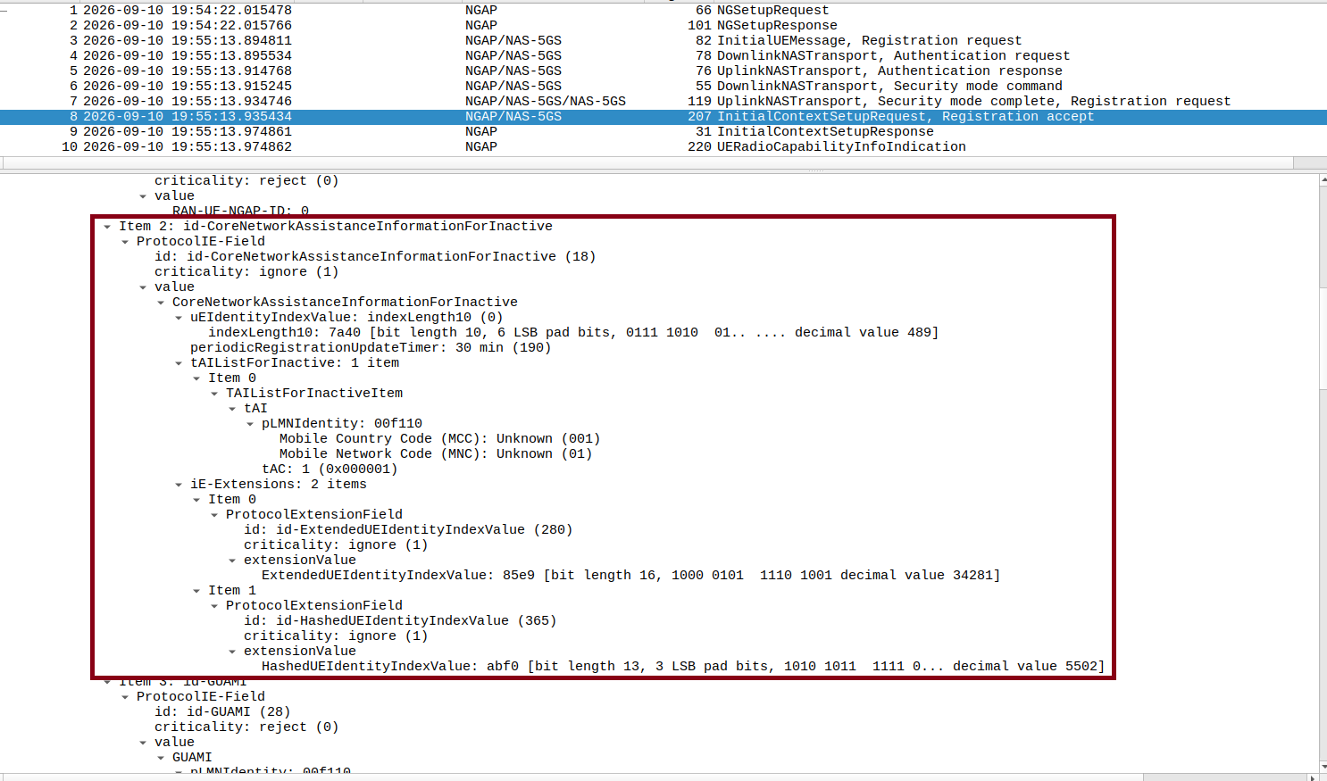
Below shows the CoreNetworkAssistanceInformationForInactive IE inside InitialContextSetupRequest in the NGAP packet capture in Wireshark. The image below confirms that the AMF has provided the assistance information required by the OCUDU gNB.
Verify UE Capability for RRC Inactive
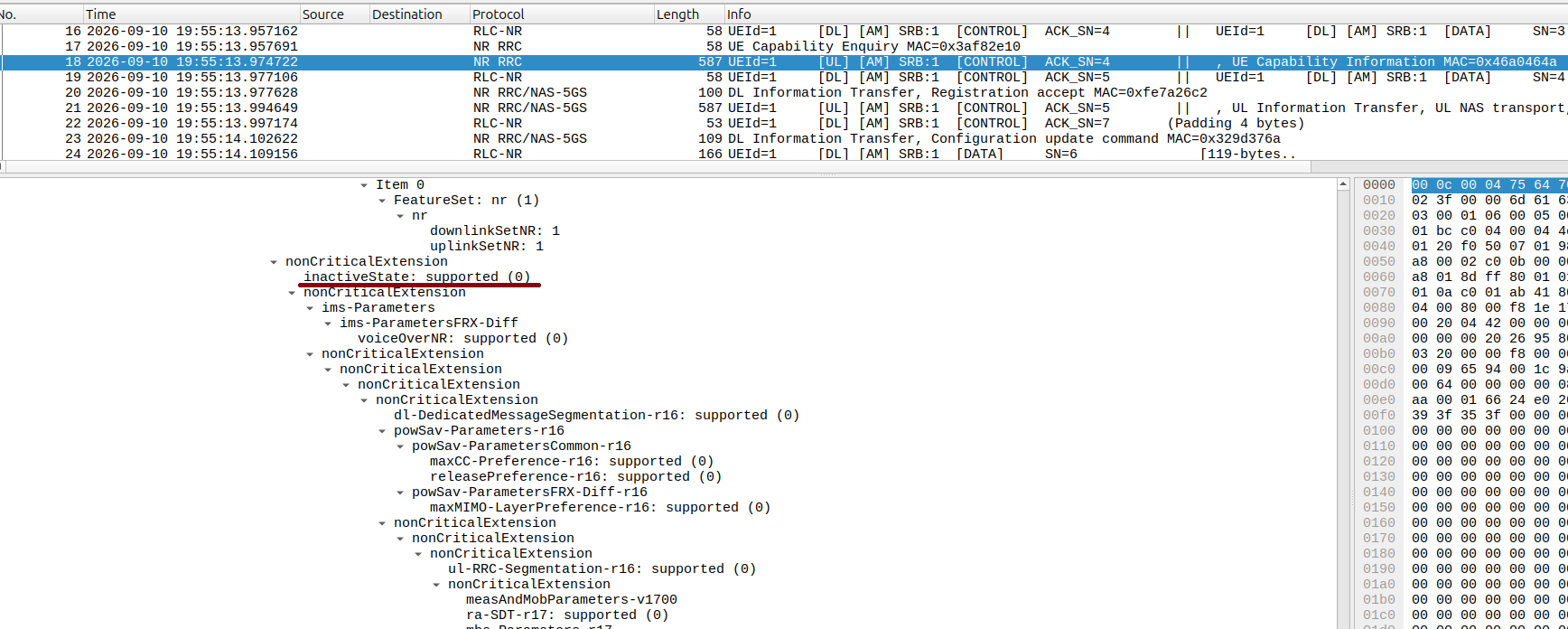
The UE Capability Information message in MAC packet capture should report inactive supported, which indicates the UE can support RRC Inactive operation.
Verify the Transition to RRC Inactive
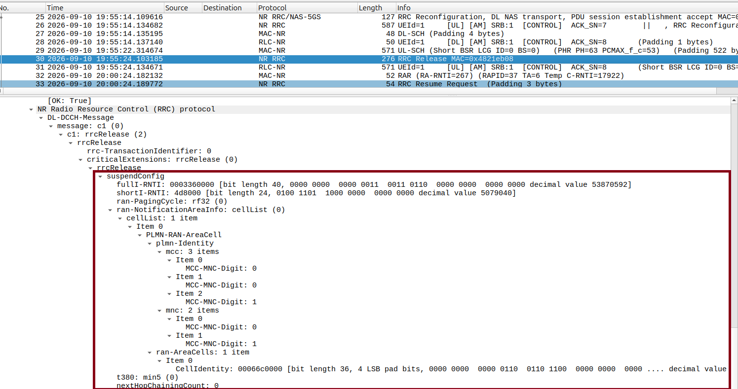
The RRCRelease message should contain the suspendConfig IE, which includes the information required by the UE to resume the suspended connection.
Verify the RRC Resume Procedure
Inspect the MAC packet capture in Wireshark. The image below shows the RRC messages exchanged during the emulation:
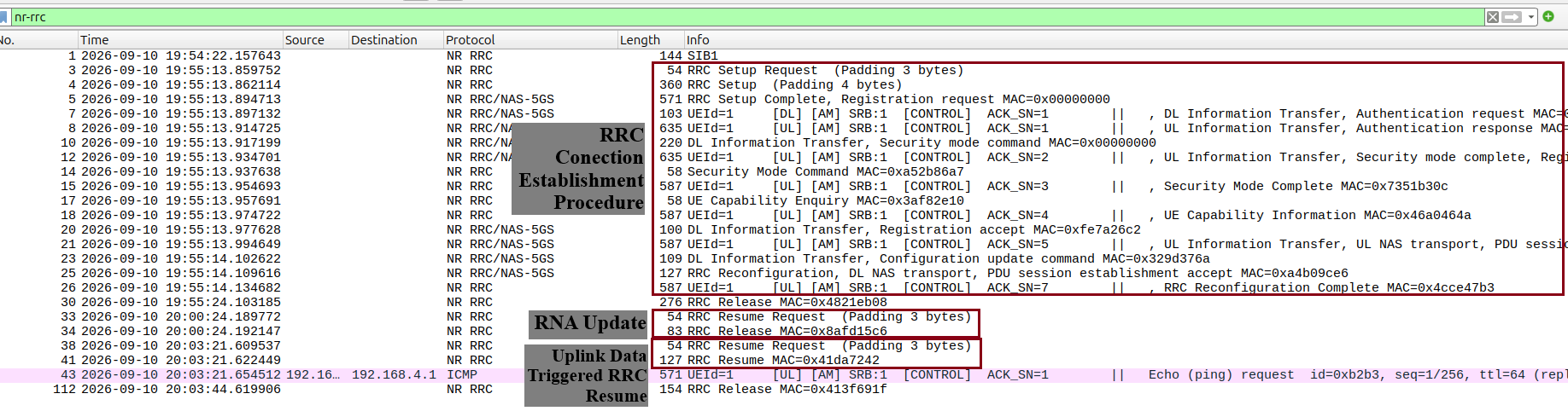
The RRC connection establishment procedure creates a UE context first. The inactivity timer (10 s) fires next. This releases the RRC connection and transitions the UE from RRC_CONNECTED to RRC_INACTIVE. The RNA update procedure resumes the RRC connection after T380 period (5 minutes). The gNB immediately releases the RRC connection again for the RRCResumeRequest. This returns the UE to the RRC_INACTIVE state. Finally, the ping command generates uplink data to resume the RRC connection.
Troubleshooting
ZMQ setup
Amarisoft UE in ZMQ based setup may not connect to OCUDU if the time between gNB bring up and UE bring up too large. So its advised to run immediately after running gNB for better results.
Reference clock for over-the-air
If you encounter issues with the UE not finding the cell and/or not being able to stay connected it might be due to inaccurate clocks at the RF frontends. Try to use an external 10 MHz reference or use a GPSDO oscillator.
5G QoS Identifier
By default, Open5GS uses 5QI = 9. If the qos section is not provided in the gNB config file, the default one with 5QI = 9 will be generated and the UE should connect to the network. If one needs to change the 5QI, please harmonize these settings between gNB and Open5GS config files, as otherwise, a UE will not be able to connect.
Next steps
- Testing handover — move a UE between two cells.